CRIMPED TERMINATIONS
SHIELD CRIMPS
shield crimps
SHIELD CRIMPS

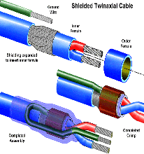
Shield crimps are used to mechanically "finish" the end of individually shielded cables.

For ground shield terminations, the crimp assembly will have a grounding wire attachment, allowing the cable shield to be elctrically terminated to ground.

For floating shield terminations, the crimp assembly will be completed without the ground wire attachment.

See Section 2.01 "Crimped Terminations - General Requirements" for common accept/reject criteria.

interim assembly view ground shield termination

ACCEPTABLE

INTERIM ASSEMBLY VIEW

Outer crimp ring has been deformed only by tool indenters, with indents properly located and symmetrical. Inner crimp ring has not been deformed. No exposed base metal. Ground wire has proper insulation spacing and end is visible.

NASA-STD-8739.4 [11.5]

ACCEPTABLE

GROUND SHIELD TERMINATION

Heat shrink sections are properly installed, tightly shrunk, and the termination is visible. Overlaps meet minimum electrical spacing. Ground wire exhibits proper bend radius and strain relief.

NASA-STD-8739.4 [7.3.22], [9.8.1], [9.9], [11.5], [19.6.1]

floating shield termination ground wire overhang

ACCEPTABLE

FLOATING SHIELD TERMINATION

Heat shrink tubing is properly installed, tightly shrunk, and the termination is visible. Overlaps are of sufficient length to meet minimum electrical spacing.

NASA-STD-8739.4 [9.8.1], [9.9], [11.5], [19.6.1]

MANDATORY

GROUND WIRE OVERHANG

The end of the ground wire shall be flush with the outer ferrule edge, but shall not overhang the inner ferrule edge.

NASA-STD-8739.4 [11.5]

NASA WORKMANSHIP STANDARDS
NASA logo Released:
03.30.2001
Revision:
Revision Date:
Book:
2
Section:
2.10
Page:
1


CRIMPED TERMINATIONS
SHIELD CRIMPS (cont.)
ground wire orientation ground wire insulation gap

PREFERRED

GROUND WIRE ORIENTATION

The ground wire should be dressed to the rear of the crimp termination, to allow the inclusion of a stress relief loop in the completed assembly. The ground wire may also dress forward, provided sufficient stress relief is provided.

NASA-STD-8739.4 [11.5]

ACCEPTABLE

GROUND WIRE INSULATION GAP

The ground wire insulation gap shall be   < 0.76 mm (0.030 in.). The minimum gap shall be flush with the edge of the outer crimp ring.

NASA-STD-8739.4 [11.5]

inner and outer ferrule spacing minimum and maximum shield and braid gap

ACCEPTABLE

INNER/OUTER FERRULE SPACING

The inner ferrule may extend a minimum of flush with, and a maximum of 1.7 mm (0.07 in.) beyond the front edge of the outer ferrule.

NASA-STD-8739.4 [11.5]

ACCEPTABLE

MIN./MAX. SHIELD/BRAID GAP

Min.: The placement of the crimp rings shall be such that the dress of the shield stranding is not subjected to flexure stress or tensile load.
Max.: The maximum shield gap shall not exceed 0.76 mm (0.030 in.).

NASA-STD-8739.4 [11.5]

nicked shield strands excessive ground conductor length

ACCEPTABLE

NICKED SHIELD STRANDS

Nicked shield strands shall not exceed 10% of the total number of strands.

NASA-STD-8739.4 [19.6.2.b.2]

UNACCEPTABLE

EXCESSIVE GROUND CONDUCTOR LENGTH

The ground wire end shall be flush with the outer ferrule edge, but shall not overhang the inner ferrule.

NASA-STD-8739.4 [11.5]

NASA WORKMANSHIP STANDARDS
NASA logo Released:
03.30.2001
Revision:
Revision Date:
Book:
2
Section:
2.10
Page:
2


CRIMPED TERMINATIONS
SHIELD CRIMPS (cont.)
improper alignment of the ferrules improper ground wire insulation gap

UNACCEPTABLE

IMPROPER ALIGNMENT

Improper alignment of the ferrules reduces the reliability of the termination and indicates the use of an incorrect crimp positioner and/or improper insertion into the crimp tool.

NASA-STD-8739.4 [19.6.2.b.4]

UNACCEPTABLE

IMPROPER GROUND WIRE INSULATION GAP

The ground wire insulation gap shall be   < 0.76 mm (0.030 in.). The minimum gap shall be flush with the edge of the outer crimp ring.

NASA-STD-8739.4 [11.5]

improper heat shrink length improper strain relief and improper bends

UNACCEPTABLE

IMPROPER HEAT SHRINK LENGTH

Heat shrink tubing conforms to crimp outline, but does not extend over the wire to provide any sealing or strain relief.

NASA-STD-8739.4 [9.8.1], [9.9], [19.6.2.b.8]

UNACCEPTABLE

IMPROPER STRAIN RELIEF/IMPROPER
BENDS

Wiring must be properly dressed to ensure a reliable termination. Wire bends shall meet minimum radius bend requirements.

NASA-STD-8739.4 [7.3.22]

inner ferrule damage and distortion nicked shield strands

UNACCEPTABLE

INNER FERRULE DAMAGE/DISTORTION

The inner ferrule shall be sized so that the inward distortion caused by the crimping process will not affect the insulated wires it surrounds.

NASA-STD-8739.4 [11.5]

UNACCEPTABLE

NICKED SHIELD STRANDS

Nicked shield strands shall not exceed 10% of the total number of strands.

NASA-STD-8739.4 [19.6.2.b.2]

NASA WORKMANSHIP STANDARDS
NASA logo Released:
03.30.2001
Revision:
Revision Date:
Book:
2
Section:
2.10
Page:
3


CRIMPED TERMINATIONS
SHIELD CRIMPS (cont.)
uneven shield coverage

UNACCEPTABLE

UNEVEN SHIELD COVERAGE

The shield braid shall be dressed to provide uniform coverage and dispersion. Uneven coverage may result in electrical interference in sensitive circuits and may interfere with the reliability of the crimp assembly.

Best Workmanship Practice


NASA WORKMANSHIP STANDARDS
NASA logo Released:
03.30.2001
Revision:
Revision Date:
Book:
2
Section:
2.10
Page:
4


Click here for printable .pdf file for Section 210 Crimped Terminations Shield Crimps click here to download Adobe Reader Click here to email the author of the Pictorial Reference Handbook
Need a printed copy?
(May take a while to load.)

Requires Adobe Reader.
Need Adobe Reader?
Click here to download.
Questions? Suggestions?